Posts

Showing posts from 2012

Christmas Eve Arduino Fun!

Watch "Guinness Christmas Lamp - Arduino" on YouTube More nonsense!

Raspberry Pi Cardboard Box

Image
Another case design. Made from an old manila folder so that's recycling too!

Raspberry Pi Guinness Grotto!

Image
This is a simple little project with a great back-story. About 15 years ago, my late father David Walsh was having a pint in the Ormeau Arms, a.k.a. Fealty's, bar on High Street in Bangor.  This was his local and by then the only bar left in Bangor that you could take a dog into.  I remember seeing them put an ashtray on the floor with some beer in it for the dogs.  Anyway it was Christmas time and there was a big tree behind the bar with a string of these promotional Guinness Christmas lights on it.  My da pestered the barman until they gave him one of the Guinness glass shades and it became a family in-joke on the Christmas tree at my mother's house every year. With my father and then my mother passing and clearing the house, the Guinness glass went missing until last week when I found it in amongst some spare bulbs for a long-gone string of lights. It needed a 21st century upgrade! The RaspberryPi is on the left, connected with my home-made GPIO connect

RaspberryPi I2C Level Shifter

Image
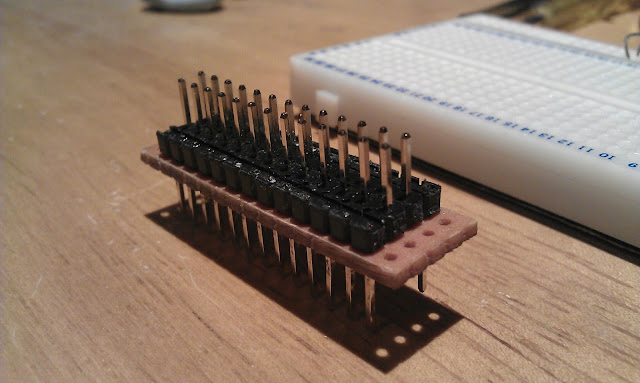
A small project, but vital when you're experimenting with the RaspberryPi because the RPi's General Purpose Input Output (GPIO) pins operate at 3.3v rather than 5v.  There are several ways around this and I'm using a ULN2003 chip at the moment to play with the GPIO in output mode, but for I2C bus experiments, the ports are bi-directional, so the level-shifter needs to work both ways too. The circuit is a novel application of a MOSFET, in this case a BSS144 to provide a bi-directional level-shift circuit.  I'd used the same approach once before to connect a 3.3v serial USB module to a PIC microcontroller operating at 5v TTL levels, which worked fine, but I wanted a design for a reproducible and reusable module that can be plugged into a breadboard. The only problem with the design (for me) is that the BSS144 is a tiny surface-mount component and is easy to lose so a fine-tipped soldering iron, a good magnifier and pair of tweezers are the order of the day.

DIY Arduino

Image
A few weeks ago I finally got around to buying an Arduino microcontroller board.  There's no doubt this is the easiest way to get into microcontrollers for beginners and all of the software and hardware designs are open source, how cool is that?  Pretty quickly I found a video output library for the Arduino and have been experimenting with that as it would make a great basis for a retro video display.  I wanted to see about building a standalone video generator that would connect as a module to other microcontrollers via either RS232 or maybe as a slave I2C device.  I purchased a DIY Arduino kit for 8 GBP on eBay, basically just an AT MEGA 328 microcontroller with the serial bootloader pre-loaded and a USB-to-TTL RS232 adaptor.  This is it breadboarded and almost ready to connect to a video monitor, except I had unexpected problems with compiling the TV-OUT sketch (script, program) on my Linux workshop machine.  It worked okay on Windows, so I'll need to investigate this furthe

Pringles Tin Speakers

Image
During the summer, Pringles crisps were giving away free speakers that clip on the top of an empty Pringles tin.  The only drawback was that for a stereo pair I'd have needed to eat my way through 6 boxes of Pringles, and I'm more of a Tayto guy myself.  Anyway, we went to see 'Skyfall' last month and my 13-year-old darling daughter got me to buy her 2 of the small cartons of Pringles for the film (costing about as much as 6 big tins in Asda!).  I hung onto the empty boxes and discovered that a pair of speakers I had reclaimed from some old thing were a perfect fit for the Pringles tins.  I soldered lengths of twin speaker cable to them and glued them onto the top of the tins with epoxy.  To round them off I found some 'funky foam' in my son's craft box (I owe him a sheet now) and covered them with it.  They sound amazingly good considering what they are and they look pretty contemporary too. So I was good to go and the mini CD player I was going to use

Nearly there...

Image
The stove is now surrounded by a really outstanding hearth, with all the pipework boxed in using fireproof board and tiled with gloss black designer tiles. This has been 4 years in the making, but we are finally there. From a technical angle, the stove and oil boiler are now properly valved (after 3 attempts!) so that they don't interfere with each other. We had the oil boiler repaired in October and new baffles, jet and pump were fitted to hopefully give it another few years service life. Interestingly, priming the radiators for 5 minutes with the oil before turning the stove pump on seems a good strategy. I'm very keen now to incorporate this into the controller unit I'm designing. Off to a Raspberry Jam later!

RaspberryPi GPIO Adaptor

Image
I needed a neat way to connect the RPi to a breadboard and came up with this using an old 26-pin floppy drive cable, an off-cut of tri-pad stripboard and some pin strips.

Found TV

Image
Last week I'm driving along and saw a flat screen TV fly-tipped at the side of the road. It looked like it hadn't been there too long so I snaffed it into the boot of the car. I let it dry out overnight beside a radiator and then plugged it in. Surprise surprise, the backlight was flickering and there was a bad buzz so I was pretty sure that the inverter board was knackered. Hoking in the spares box I found an inverter board from a TV that had suffered a cracked screen. A bit of dodgy test wiring and a connection to my old Sky box and there's Masterchef! The screen is still drying out and I'll need to tidy the wiring, but there's a free LCD TV. The old inverter is integral to the power board, but the circuits are all the same so I can disarm the old inverter and run 12v, GND, Adjust and Enable connections to the new inverter.

Old Skool

Image
I got this meter on eBay for a fiver. I just took a notion for an old school classic meter because it reminded me of my grandfather who was a radio amateur from the 1920s and built his own radio kit.  In his house in Cushendun there was this amazing shortwave transmitter he'd built.  It was in a hammered finish metal case about 5 feet high and had proper dials and meters on it, like something from a 50s science fiction film. I've always loved that retro stuff. Anyway my meter reads 0-5mA and with a 1kOhm resistor in series it reads the 5 volt PWM output from the Arduino perfectly.  I have a notion to use it as a thermometer readout although it would look equally great in a car.

Interceptor

Image
Just a quick post.  I bought an HDMI adaptor for my Android tablet (4.0 ICS), which has an HDMI C 'Mini' connector.  I thought this was the most versatile approach as I have a few standard HDMI cables of different lengths and an HDMI-DVI cable for the RaspberryPi.  Anyway, here is the tablet computer hooked up to the 21-inch TV in the kitchen and if you look closely you can see the Android screen there with apps and the fish-pond wallpaper. My son and I have been using this to watch old episodes of the bonkers-but-brilliant 1989 TV game show 'Interceptor' on YouTube.  If you have never heard of 'Interceptor' then you are in for a treat.  Think 'Treasure Hunt' meets 'Crystal Maze' (it was made by the same production company) with a maniac in a black leather trench coat chasing you around the English countryside in a helicopter while jolly-hockey-sticks Annabel Croft gives you directions to the loot.  Unfortunately there were only 8 episodes ma

RaspberryPi Access Point

Image
This is the RaspberryPi (RPi) running as an access point (AP).  Okay doesn't look like much, but this is pretty advanced stuff, yet as always relatively simple in Linux once you know what to do.  The key is the D-Link DW-140 wi-fi dongle perched on top of the RPi, which can act as an access point.  Not all wi-fi dongles can do this, but loading the 'iw' wi-fi tools package in Linux and running 'iw list' outputs diagnostics which will tell you if a connected dongle can run in AP mode. All the details are helpfully on this guy's blog - http://sirlagz.net/2012/08/09/how-to-use-the-raspberry-pi-as-a-wireless-access-pointrouter-part-1/ Now my motivation for looking into this was the desire to use one of the tablets as a front end for a vehicle diagnostics system. Problems - Cheap Android tablet computers don't have serial or Bluetooth capabilities; Without Bluetooth or serial how do you communicate; While these can be added, it is complex as the An

Netbook Upgrade

Image
I'm not usually into buying things before anyone else, but 4 years ago I took a punt and bought my wife one of the very first Acer netbooks as a birthday present.  This was the first serious netbook with a 9-inch screen after the 7-inch Asus which had arrived about a year before.  The Asus screen was just too small for a computer although it paved the way for all sorts of things including OEM distribution of Linux.  The Acer A110 had 512Mb of RAM and an 8Gb solid-state drive, which some people predicted wouldn't last (they have been proved very wrong).  After 2 years constant use the wee Acer was replaced with a new one with more memory and a hard disk drive, but I always fancied upgrading it. The computer was pretty hard to upgrade as it had to be completely taken apart and one internal tiny Phillips screw was very tight.  In the end it needed to be removed by cutting a slot across it with a MiniCraft drill fitted with a circular cutting blade and then using a thin screwdriv

Raspberry Gambas

Image
Thanks to the work of some guys on the RaspberryPi forum, Gambas3 is now running on the little computer.  So after a couple of hours work installing a new OS image with Gambas3 on it and getting the hang of it I have managed to get the bar chart program running.  As before the Psion II is pretending to be the data-logger and is sending out random data in the format I have currently settled on. It works pretty well, but the RPi is being pushed close to its limits here and the mouse has a habit of becoming inactive.  Ultimately I think I will need to learn Python and go down that route using the widget approach to get a GUI output, but there is a pretty steep learning curve there. The next step is to finish off the touch monitor and get a module (driver) for the touch panel and the calibration program running on the RPi.

Powered USB Hub - £2

Image
 I bought a couple of these little USB 2.0 hubs for £1 each in PoundWorld intending to adapt them to be powered hubs for use with RaspberryPi computers.  Alan here ( http://pihub.blogspot.co.uk/2012/06/raspberry-pi-power-supply-and-powered.html ) beat me to it, but I wanted to give it a go with a flying power socket.  As usual, heat-shrink sleeve comes in to save the day. I didn't like the original USB lead and plug so I bought a USB-to-Micro USB cable (again for £1) and cut it in half.  One end goes to power the RPi and the other is the input USB. The input USB has only 3 connections made, the red power wire is cut short and ignored.  I did connect the ground (GND) wire though because the purist in me doesn't like the idea of floating grounds (blame my MSc).   The output for power to the RPi via the micro USB plug only has the GND and +5v connections made and the other 2 signal lines were chopped short and ignored. The power input was made from a DC power socket sal

Hold on...

The workshop is in a right state this week as a result of trying to clear out stuff and move some furniture back into the house for a study I am decorating, which should hopefully be finished tomorrow now that I have some more white emulsion paint. I was working on my Silvercrest/LG TV recorder this evening, which has developed a fault with the DVD recorder part.  The hard drive end works fine, which means it is worth trying to repair.  The odd thing is that I cleaned out the DVD drive, cleaned the lens on the laser and blew some air round everything and hay presto it started playing a DVD again out in the workshop.  15 minutes later I took it back into the living room and hey un-presto it has gone kaputt again.  This is typical.  Maybe the house just has bad karma. I will investigate further. DVD Drive model - MEZ36295702

At last something that works...

Image
Okay, I now have a working Gambas program that will read a formatted RS232 data stream and display the data as a dynamic bar chart.  To test this I rigged up my trusty old Psion II LZ and wrote a little OPL (Psion programming language) script to output a suitable random data stream.  The project is running on a laptop at the minute because I haven't gotten Gambas onto the RasberryPi yet and apparently it is quite slow, but I love the graphics. The system is designed to work with 8 sensors and the data is 10-bit (values between 0-1023), so the format of a data frame is (at the moment) 18 bytes as follows - - 'A' as the start character, the program reads data and ignores it until it receives an A; - Pairs of bytes representing the upper and lower 5 bits of the 8 10-bit data values; - 'B' as a terminating character. To avoid confusion and make debugging easier, the 5-bit data is sent as bytes in the decimal range 32-63.  The ASCII codes for A and B are 65 an

50 Shades of Raspberry

Image
I got around to finishing off the repair of the DVI/HDMI monitor and here it is re-assembled and running a test with the RaspberryPi computer.  The RaspberryPi is temporarily in a simple Lego box to keep it from being damaged.  The connecting HDMI-to-DVI-D video cable came out of DiscountNI of all places for just £2.99, which was a real result. The small (and very tidy) power supply came out of an obsolete PC and I re-wired the mains input and removed all of the output connections before re-connecting one disk drive power cable with 2 Molex male connectors on it to provide 12v and 5v to the monitor. At the monitor side, I stripped out the parts connecting the broken internal power supply to the main circuit board (mainly the isolating transformer) and re-cycled a Molex female connector from an old DVD drive as a power input connection.  Some heat-shrink sleeving and couple of cable ties to neaten things up and the monitor is now running off the external power supply.

Raspberry Jam

Image
Well, here's the proof that I finally got hold of a RaspberryPi computer (for £25 including p&p).  The odd arrangement of the monitor has its own story of course.  I was given this Hanns-G LCD monitor recently by another kind Freegler, but the power supply was faulty.  What made it worth fixing was the DVI interface which can be directly connected to HDMI and HDMI is what the RaspberryPi outputs. So I took it apart and found that it was basically running off 12v and 5v which was easy enough to test rig from an old mini-PC power unit.  The monitor has a good crisp image and once I tidy the wiring up a bit it will be fine for use with the RaspberryPi.  The HDMI-to-DVI cable was £2.99 out of a local discount shop.  Always worth a look in Poundland, World of Pound, Home Bargains and the other discount shops, you never know what they have. For the time being, we built a Lego box for the RaspberryPi, pretty much from scratch.  The sticker on the top was to hint at the compu

At the coal face

Image
An early analysis has shown that we have saved £750 this winter in reduced fuel costs by installing the new multi-burning stove.  Taking into account that this was a mild winter, the whole install will break even in just over 3 years.  The oil tank was filled a year ago and is still 1/4 full (so around 900l used) and we have used roughly a tonne of coal, giving a total fuel cost of around £750 for winter heating.  This compares with around £1500 in the last winter when we were on oil only. Phoenix Gas have been delivering a mail shot in our area (again) offering a piped natural gas service.  When I 'phoned up (again) to order it they told me (again) that it isn't available in our area.   Should they consider targeted marketing perhaps?

DIY Touch Screen

Image
This mini touch screen is now working (incredibly) and gives some ideas on how a screen of any size could be interfaced to the Raspberry-Pi, when it arrives. There are no special interface ICs being used here, just 4 transistors and some discrete components to let the PIC microcontroller (18F4620 in this case) control the power into the resistive panel and then read the relevant voltage to determine the X and Y coordinates of the pressed point. For simple applications like an on-screen keypad, ON/OFF control and so on, this is adequate and with improved software (averaging and use of interrupts) it could be much more accurate. The interface circuit requires 4 lines of I/O, 2 digital outputs and 2 analogue inputs. The touch screen was salvaged out of a cheap PDA which had stopped working and the graphical LCD ( GLCD ) is a standard KS0108 driven via a bespoke I2C 2-wire interface I bought on eBay although in future I would just interface one of these directly to the PIC.

Idling along

Image
The MR2 has suffered idling problems almost since the day I bought it 10 years ago. It will run along fine for a while until it warms up and then the idle gets erratic after a while, it will over-rev and then conk out at junctions just to embarrass you. Last year I cleaned up and checked over all the plugs and leads and put a new distributor cap and rotor arm on and this improved things a bit, but not much, so this year I'm looking (finally) at the induction side of things. This is the Air Flow Meter ( AFM ) on the bench. This is a heavily-made piece of kit compared to the rubbish plastic hot wire ones you get nowadays. It tested out fine and cleaned up nicely. This is the throttle body removed and cleaned up a bit. The throttle position sensor ( TPS ) is the black thing on the left and the Idle Speed Control Valve ( ISCV ) is the part on the right. The TPS seems to be okay although it needs adjusting a bit, but when I took the ISCV off, all was revealed (maybe). There are

Back to the Future

Image
A year ago I started playing around with Google App Inventor and built a few test applications for my old £20 Android tablet . App Inventor has been taken over by MIT, who built the Apollo Guidance Computer that took men to the Moon, so they have a fair idea what they are doing and it has been re-launched in a new beta form. Now I have the Scroll Essential tablet, I decided to go back to this and it looks quite good, but the problem is that the Scroll has no drivers for either Bluetooth or Serial-USB so it can't communicate with anything. I've been investigating how to load modules (drivers) into the Android kernel, but it is no trivial task and might not be possible; a real shame as this would be the ultimate sub-£100 car computer. App Inventor (MIT) running under Windows XP

The Venturer monitor in the raw

Image
This is the pin-out for the Venturer monitor as it comes with the DVD. The little DIN plugs are 9-pin, but as you can see in my notes above, I replaced these with standard 5-pin DIN plugs carrying power, video and stereo audio (waste of time as there is only one speaker in the case!) After a while I went back to these monitors and stripped them out again. This is the inner section of one of the Venturer 6.2" monitors, the part that swivels up and down, removed from the outer case. Only 4 connections are needed to drive this and they are marked on the reverse of the circuit board - V+; GND; Video; Video GND. You can also rig your own colour and brightness controls if needed because all the necessary connections are available, but they may not be needed as the monitor defaults to usable settings. It has no back to it, but as this one will be cased or in a dashboard that didn't worry me. There is a photo here that shows the back of the monitor and the control signals (bright

Dell Axim Bargraph

Image
I had a bit of time today to experiment with Embedded Visual Basic and reasonably quickly I got this bar chart display up-and-running. The test data was coming in as a sequence of characters via a Bluetooth serial port. This is a big start of getting something working that can communicate with the Bluetooth enabled data-logging unit I've been tinkering with for months.

Opto-tachometer

Image
Motor sub-assembly taken from a broken Canon printer. I've seen several of these opto -tachometers (or position sensors), but I liked this one, especially as it was so easy to test. There are only 4 wires for the sensor which turned out to be +5volts, GND and 2 sensor output wires. If you look carefully you can just see the plastic disc driven by the motor which has a lot of fine black lines on it which interrupt the beam of light in the sensor. The beam is visible rather than infra-red which is handy because you can see it so that means something is working! With the motor running and one sensor connected to a multimeter set to measure frequency, I got a steady 6.3kHz and when a bit of resistance was applied (i.e. a finger and thumb) the speed reduced and the frequency with it. Handily the meter also reads duty cycle (ON/OFF ratio of the pulses) and I got 49.5%; almost 50/50 cycles. Interestingly on the other sensor wire I got... 51.5% as would be expected so I'm guessing t

Update on the touch monitor

This is tantalising... I found some data on driver chips used on these low-cost monitors and some of them have an I2C connection for sending pixel data directly to the screen. This may be to allow text or graphics overlay. Anyway the chip on my 7" screens is an AR05C-LF and there are millions of these in stock in the far east, but I can't so far find a data sheet for this chip or its sibling the AR05CA-LF. Being able to send digital pixel data via I2C directly to the screen would be, well, brilliant.