Posts

Showing posts from 2010

Wind Up

Image
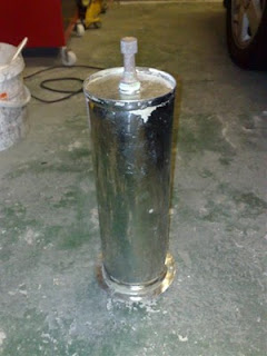
I was having a sandwich lunch down at Tyrella beach on the Co Down coast back in late September and went for a walk afterwards and found this thing half-buried in the sand. It turned out to be a boat immersion heater of some sort (I don't own a boat so maybe someone can enlighten me). There was an electrical element and 2 pipes coming out of the top and the bottom connection you can see in the photo. It must have been thrown overboard (assuming the boat it was on didn't sink!), maybe after being replaced. It had been in the sea a while by the looks of it, but being stainless steel it has started to polish up quite nicely. The lid is held on by 6 bolts and I gutted all the old gubbins out of it to get the cylinder itself. Willis Solasyphon Anyway, the basic plan is to wind 1 or 2 tight coils of 8mm microbore copper pipe like in the photo above and make a heat exchanger out of the cylinder. I've had a go at winding this type of coil before and it isn't easy, but I'd

Custom Bass Box

Image
I spent a couple of days working on this custom bass box for the MR2 based on parts from the cheap boom box I got in Larne a few weeks ago for £20. I decided to strip the speakers out and dump the box and as luck would have it I acquired 4 old stereo speakers for stripping and found a load of light MDF in a skip. I got acoustic wadding, a cross-over circuit and a nice pair of tweeters from an old pair of Awia speakers (the main drivers had dozed after getting damp) and cobbled all of this into the speaker box you see in the photo. A massive improvement on the pants 1980s set-up in the MR2 and the first time the car has had some real bass. The head unit is a Kenwood 4 x 50 watt with with MP3-CD capability and is ideal for a weekend car.

No joy with the XDA

I spent a bit of time working on the XDA without success. I sorted out a serial connection and used Bluetooth to transfer some test programs to the 'phone, but trying to access COM 1 just gets an error as if the port doesn't exist. I tried all the ports from 0 to 15 with a simple serial reader and got nothing. Checking the wiring to the board all seems well, but it is always hard to tell for sure. I'll give it one last check before giving up. I got some technical stuff about the iPaq online and have details of how to dismantle it safely and will see if the screen flicker is maybe just a loose connection.

XDA Lives (ish)

Image
On the bench with 2 power wires now soldered to the pads on the main board. This was quite easy using a magnifier because there were 3 pads for +VE and 3 for GND side by side so three times the area to solder to. Here's the XDA charging from the power supply and the power light turned yellow as well. It remains red with no battery, so I'm guessing you need a battery installed to make this thing work. Finally, here's a low shot to show the poor XDA is half naked, in fact it's backless and its guts were hanging out. Only the weight of the unit was keeping the battery in contact with the main board. I managed to solder one of the RS232 wires on after this, but not the other one, it is very fiddly. I'll have a go tonight or tomorrow again and report back what happens.

XDA 2 Connector

Image
Another kind donation, this time of a nice O2 XDA 2 PDA/Smartphone (HTC Himalaya), running Windows Mobile 2003. The owner told me the 'phone wasn't working and the battery wouldn't charge, but it was quickly apparent that the fiddly little connector at the base of the 'phone wasn't right. The cradle had an option to charge a second battery in the cradle itself, so I took the battery out of the 'phone and charged it that way and the unit powered up perfectly and did its thing. A quick search revealed the excellent XDA Developers website with a huge wiki and a forum and I quickly had an HTC service manual for the 'phone and the pin out for the connector. I was thinking of fashioning a serial cable in the same way I did for the iPaq using the power plug adaptor (the iPaq and XDA use the same plug, but different pin out), but the power adaptor was damaged as well making me think the 'phone had suffered an accident in the connector department (always painf

Pimp my...what??

Image
This was an impulse buy! I got this 'boom box' for £20 in B&M Bargains in Larne. The sound quality isn't bad (the speakers claim to be rated to 300W), but I'm not too sure where I'm going to fit them. Even better was when I found out you can hook up a 12 volt feed and they light up with a dazzling display of blue LEDs! Anything is better than the tinny rear speakers behind your head in the MR2, they start buzzing the minute anything lower than a contralto dares to be played through them, so a way will be found to shoehorn these in somehow.

C Spot Run (under DOS)

Image
Well I have temporarily shelved the Psion II while I go back to looking at the gutted laptops for a more colourful display. I'm working on Borland C++ under DOS (no sniggering at the back, this is serious) with a full (wait for it) 16 colours, but that's all I need. There are good reasons for this, the main one being simplicity. The laptops are all Pentium I or late 486 so they need simple software and it will be keypad controlled so no need for a complex GUI. All I need is something that will read my data stream from RS232 and display it with some storage and analysis. And here we have the first attempt, RPM and throttle position (TPS) on screen. Okay I'm cheating a bit because the data is coming from the bench test rig, but it's a step forward. I've also had this displayed on the 7 inch LCD screen via the VGA-to-Video box, but at 640 x 480 resolution it is hard to read. I think experimenting with the colour scheme might help, but using composite video is unfortu

PSION II Datalogging, Bar Graph

Image
Well thanks to some pointers from Boris I got a working bar graph (progress bar) on the Psion II and using machine code too. And I'm over 40. The Psion's RS232 capabilities are really put to the test in OPL though, the buffer fills quicker than the OPL can process it, so I trimmed the amount of data from 64 characters to just 18 without compromising on data. This allows the datalogger to send 8 channels at 10-bit resolution and the Psion to identify the channel to be displayed. If I go any further with this I want to write more if not all of it in machine code especially to make sure the serial buffer is clear at the beginning of the program, which at the moment is causing problems. The full set up on the bench. Eventually I want the Psion up in the cockpit of the car (okay, sitting on the dash) or as a hand-held garage diagnostic box and the PIC and so on will be permanently attached to the ECU in the car. Or something like that.

Wooden Car Ramps

Image
Here's my patent wooden 'gentle' car ramps made from treated decking. Celica ST-165 calipers fitted to my MK1 MR2.

Psion II in on the act

Image
I have been meaning to press my old Psion II LZ into service for a while. Now if you go way back in the blog you'll see that I was building a parallel port interface a while back for the Psion , but early tests revealed that it was painfully slow and also there were some bugs in the operation of the port, so I temporarily shelved that. Having mastered RS232 on the PIC using JAL (which is just so good I had to order the book), this opened up another avenue, communicating serially with the Psion . So here we go, the Psion II is receiving the data stream from my 16F690 A/D device and selecting one of the 8 channels to display. I experimented with displaying a bar graph on the Psion LCD, but once again, the speed was against me. I fear I may need to look at some simple assembly to achieve that one. Here's the full set-up with the Psion connected to the PIC via a (long) null modem cable, which would be spot on for connecting to my diagnostic system in the Toyota and taking

Stupid is as stupid...

Image
Well after looking at the test circuit again I realised that I was using a pin on the PIC for 2 incompatible purposes, driving the RS232 communications and the enable line for the LCD display. Doh . One minor change and it is all working. I discovered a handy procedure in the JAL libraries to display a progress bar or bar graph and although I could write my own it was quicker to just use this one. Voilá , a bar chart showing the analogue value, in this case a light level detected using a light-dependent resistor. The LCD is only for testing and playing purposes, the real beef is the RS232 connection, shown here on an HP iPaq running Pocket Zeus Lite as a basic serial terminal. The PIC is programmed to output the analogue value once a second (roughly) in a standardised 8-character format of C1V0099# [C = channel; V = value (10-bit, range 0-1023); # = terminator] which can be read by anything that can understand RS232. So far only one channel is being implemented, but I'm going

New PIC

I finally got around to putting my 'new' PIC onto my new breadboard, the cool 16F690. It is very easy to rig up, only 3 external components for a minimal set-up. I wasn't sure if the Willem PCB3 programmer would work with it because the programmer is getting a bit long in the tooth, but by selecting a similar chip in the inventory it worked and I had a wonderful flashing LED. The program I wrote actually does an awful lot more than flash an LED, but that's always a good way to see something happening. Just as well because I then hooked up a 4x20 character HD 44780 display and didn't quite get what I was expecting. The display is working correctly, but the code is sending some weird characters and I suspect a timing issue, so I'll look into that. I'll sort an RS232 interface tomorrow and then we are well on the way to some tasty vehicle diagnostics.

Rocks and Roll

Image
Bit a departure this time. My wife was at a school summer fete a few weeks ago and bought our son a fossil hunting kit for a pound. Basically it was a sandstone fossil encased in light plaster with a little hammer, chisel and goggles so you could have a go at 'excavating' your fossil. Anyway, my wee fella was really taken with this and has been showing everyone his fish fossil (on the left). I mentioned this to my colleagues, one of whom studied geology at university and tipped me off to a good place about 30 minutes drive away where Jurassic fossils are easy to find. I'd never heard of this before in spite of knowing the area pretty well. One problem is that it is along a stretch of busy and fairly dangerous road where most people wouldn't bother to stop. So we set off this morning in the lashing rain, but by the time we got there it had completely dried up and we had a fun and interesting hour picking around in the rocks and came up with these fossils of ammonites and

Knocking around

I finally got around to replacing the knock sensor in the MR2 last Sunday morning. The purpose of the knock sensor is to detect 'knock' in other words engine detonation and that allows the engine management to run the car with ignition advanced pretty much as far as it can go. If the sensor is faulty on the 4A- GZE engine, the 'Check' light comes on, you get error code 52 and the car goes into a safe mode with reduced performance so as not to damage the engine. The original sensor was destroyed about 8 years ago by a careless mechanic who promptly went out of business before I could get it replaced. Just as well for him because a replacement ended up costing £150. I had tried several options to get around buying a new one including trying a wide-band one and one out of a Toyota Supra. The problem is that on cars of this vintage, the knock sensor was very narrow band and tuned closely to the knock frequency which is very specific to the engine and a function of str

Steal My Sunshine

Image
I was in Maplin's looking for miniature spade terminals and saw they had a sale on solar panels, must have been the recent sunny weather I guess. Anyway they had a big 2.4 watt one at £25 and smaller 1.5 watt ones for a tenner. Now, thinks I, two 1.5 watt panels makes 3 watts for £20, which is better value for money and I already know that solar panels can be quite merrily connected in parallel. So I bought 2 of the smaller ones to use to trickle charge the car and back-up batteries.

Sensors and Sensibility

Image
Well, I'm going to try and link up some of my interests by going for broke on an automotive project. The plan (!) is to make a more advanced version of Rob Files' famous 'Grunt Box' for the MK1 MR2 Supercharger, which overcomes a known issue with a lean spot at low RPM and high throttle. Rob's clever workaround was to use the cold start injector to squirt a little extra fuel into the engine in this condition and give it some grunt. The Grunt Box is expensive and seems to be an analogue circuit (nothing wrong with that), but I fancy a bit of PIC shenanigans. My system will give some fuel boosting and go a bit further by providing a dashboard display of 8 of the most useful engine parameters as detailed below. I would like to use a PIC16F690 running at 20MHz to do this and connect the display via RS232, but I might go mad and use an entire computer at the dash end (P1 75MHz laptop motherboard) with a 6.5" video display as basically a terminal Sensors 1 - Thro

It lives

Image
It hasn't been MOT'd in three years... It's only travelled 300 miles in the last six years... It's got twin cams, 16 valves, fuel injection and a supercharger... It's mid-engined and rear-wheel drive... It's only got 2 seats... It's got lowered suspension and adjustable shocks... It has tricked-out engine management... It can do 0-60 in 5.5 seconds... They thought it was dead... They were wrong.

Free electricity (-ish)

Image
This is my experimental recycled solar panel made from old garden night lights. I got 9 lights from nice people on Freegle (Freecycle), but unfortunately one solar cell was broken when I tried getting it out of the casing. I still have 8 which generate a decent 10 volts in bright light, more than enough to trickle charge the 6-volt wet cell you can see in the photo. The sun had gone in and I was only getting 4.05 volts at this point, but not bad for a first attempt. I reckon that an array of 12 cells x 3 (36 in total) would give a usable 6 volts charging supply for emergency lighting.

Micro Wind Turbine

Image
I've finally started to experiment with micro wind power and here is turbine 'Test 1.' It's made from bits of everthing. The blades are from a defunct ceiling fan and the hub is the base of an old desk lamp that stopped working. All the nuts and bolts came from a broken desk fan and I'll be using other parts of that for gearing and drives later on. The motor drove the radiator fan in a Japanese car and will be used in reverse, as a generator. The idea is to generate a useful 12volts to charge a couple of car batteries for emergency lighting use. As we live in a town, siting will also be a big consideration to keep it safe and so it doesn't annoy the neighbours. The blades are temporary and will be replaced by ones made from sections of 110mm soil pipe, although the angled brackets they will be mounted to are ideal for getting a pitch. I don't see the motor acting as much of a generator without being turned at high speed so I'm looking at using old bicyc

LM35DZ

I was about to buy a couple of LM35 temperature sensors and then found some LM35DZs in a box of surplus stuff I got about a year ago. These are a really easy to use component, they operate from a 5v supply and output a linear voltage at 10mV per degree C with 100 degrees giving 1 volt. I hooked one up to the PIC voltmeter project which reads 0-5 volts as 0-1023 points and got a reading of 16 which equated to roughly 7 degrees. I'll need to spend more time on this because the room was clearly much warmer than that, but when I held the LM35 between my thumb and finger the reading rose steadily.

IKEA Make Kitchens Simple

Image
This isn't the kitchen, but the utility room, which is an essential extension to our kitchen. About a year ago we were in IKEA and they were selling these worktops for £10 each in a sale, reduced from about £50. I should have bought 5 or 6, but stupidly just bought one. Cutting a long story short we added 3 wall units and one base unit with the uber-cheap plain, but hard-wearing Harlig doors. The handles came courtesy of another really decent person on Freecycle who was up-grading a kitchen and they have been incredibly useful. I got to thinking that this represents about half of a 'standard' 8 unit kitchen and wasn't that hard to fit. The main reason is that the IKEA units are very well designed for DIY, tough, but quickly assembled (20 minutes per unit) and easy to adjust once on the wall or floor. If anyone needs a kitchen fitted on a budget... :)

Door of Perception

Image
I got this door over a year ago on Freecycle and never got around to doing anything with it, partly through a lack of confidence in hanging doors and partly because I don't have a power plane. My brother-in-law got a really good Bosch plane and I borrowed that to fix our bedroom door which was sticking (I was also fitting a lock to it to give us some privacy when required!) and after getting that right I thought it would be nice to have the glass door into the kitchen instead of the cheap hollow one that was there. With a bit of trial and error and a lot of puffing and panting I got it done, not perfect, but not bad so I reckon I could do pretty much anything with doors now.

Generating Interest

Image
I recently acquired a Coleman Power Mate 6.5hp petrol generator that had been the victim of a flood and the owner was going to dump it, but gave it to me to play with. It's almost identical to the one in the photo. My son (4, nearly 5) enjoyed cleaning all the mud and grime off it and then we took the petrol tank off, cleaned it some more and set to work trying to get the engine to turn over. The whole engine and the dynamo was full of water, but we drained as much out as we could and then used the compressor to blow air through the engine and get the rest out. Some fresh oil and a liberal application of WD -40 into the plug hole and with a bit of rocking back and forth I got the piston free and turning over. There is some compression and a good spark, but so far no life so the next thing to do is take a look at the carburettor and make sure fuel is getting into it okay.

Alternative Alternator

Finally got myself into gear and got the alternator out of the MR2. Unfortunately that type isn't made any more and since there are more honest MPs than there are 4A- GZE engines in the UK, I'll just have to get it rebuilt. In the process of getting the alternator out I had to take the A/C compressor off, big heavy thing it is too. I had the A/C de -gassed a few years ago intending to remove it to reduce weight, but never got round to it. I guess now is as good a time as any.

Psion II I/O Board

Image
Just a quick update on the Psion II I/O board. The basic board is now finished and has 1 8-bit output and 1 8-bit input port and everything works as expected. The next job is to add two L293D quad half-H drivers (which makes 4 full H-bridges for 4 motors) to drive the 4.5volt Lego motors.

iPaq DIY Serial Connection

Image
I swapped a BBC Micro I had for this neat little iPaq PDA . The screen is a bit funny, but it just seems to be a problem with colour depth and on console applications isn't a problem because there are only a few colours being used. The iPaq could communicate via RS232 or USB , but this type only came with the USB cradle. A bit of research and I found the Kronos website, authors of the excellent Zeus programming environment and purveyors of fine information about iPaq connections. I was able to make up this custom connector from a broken car power adaptor which has both RS232 and power connections. The soldering was very fiddly and I used a fair bit of heat-shrink tubing to make everything neat, but it looks and works great. Now if I can get an OBD II to RS-232 interface cable, I can have real-time vehicle diagnostics on the cheap.

Turbo spin down

It was the turbo on the old Scenic RX4 (a common problem apparently due to oil starvation) and it nearly blew up just as my wife got to the garage. It's going to cost a lot to put right unfortunately, so not a great day. On the plus side I acquired a petrol generator that needs a little TLC after getting soaked in a winter flood. A bit of a strip down, a good clean and some WD40 and hopefully we'll get it back to life. More of the buggy.

Laptop Guts

Image
These are the innards from an old Pentium I laptop, maybe a Dell, I can't quite remember. Anyway the screen wasn't working properly so that was dumped and the BIOS set to switch to the VGA output by default and now we have a motherboard that will run on a single 12-volt supply (the red and black wires in the photo). Laptop batteries tend to be anything between 10 and 15 volts, but since the computers all have power management circuitry I've never met one yet that wouldn't run happily on a smooth 12 volt supply. The hard drive is in fact a 16Mbyte Compact Flash card connected using a 99p converter bought on eBay. CF cards have an IDE-type interface so they are ideal as solid-state drives. The only drawback is the relatively low number of writes they can handle before they burn out. Fine in a camera, not so fine in a PC running an OS with a swap file. Ideal if using FreeDOS or Linux from a ramdrive though. In these cases you can even write-protect the CF card in s

Web Site

Just playing with Serif WebPlus , an HTML-based web design program. Not as sophisticated as Dreamweaver and definitely not as flash as using PHP (I am not worthy), but good for quick web design jobs with minimal fuss. http://myweb.tiscali.co.uk/wiltecsystems I spent some of my weekend trying to sort out my wife's car, a 2003 Renault Scenic RX4 1.9dCi. The RX4 is an odd hybrid, a 4-wheel drive spacebus, which came along before any marketing guru thought up the concept of a 'crossover,' which seems to be a 2-wheel drive car masquerading as a 4x4. Anyway the EGR valve was clogged up and un-clogging it has made starting the car a breeze, but there is a deeper problem causing power loss and white smoke above 2000 rpm. I've narrowed this down to a turbo or MAF sensor issue, hopefully the latter...

Alternative Energy

Image
This is an old photo from 18 months ago when I carried out a few experiments with solar water heating. The Centre for Alternative Energy in Wales publish a great book on DIY solar water heating and one design uses these Stelrad -type radiators. You need ones with 4 inlet ports (one at each corner) so that you can arrange diagonal flow and then you need to paint the radiator matt black so it will become an efficient collector because white just reflects the sunlight away. The experiments were pretty successful and on a hot day the water in the radiator rose to over 60 degrees Celsius without any insulation. That's the problem unfortunately. This collector is about 2sq m which is about a quarter of what would be needed and boxed up it would weigh too much to be mounted safely on a roof. Anyway, this summer I'm going back to this idea, but I'm going to build a double collector using the other method from the CAE booklet, which is a copper pipe and vane design and wil

Car LCD test fit

Image
No wiring yet, just seeing what it looks like. I figured out why the input part of the Psion board wasn't working, I had the INs and OUTs back-to-front! Hopefully get this fixed on Tuesday and then add the H-Bridge drivers for the motors.

Electric Buggy

Image
The buggy started life as a toy Lamborghini running on 2 6-volt motors, one driving each rear wheel. When we moved house I took the opportunity to ditch the upper body which had seen better days leaving a bucket chassis. It has 2 6-volt emergency lighting lead-acid batteries wired in parallel to give a whopping 20 Ah. Most of these electric toys have batteries around 6-8 Ah. It doesn't go any faster, but this gives a much extended running time. These are the new wheels on the buggy up close. I got these hand-truck pneumatic wheels on eBay for £15 and my colleague Johnny kindly helped me adapt them to fit on the buggy. I finally got time to drill holes in the axles for cotter pins to make sure the wheels won't fall off. It's unlikely this would happen because the washers behind them are a very tight fit, but better to be sure where children are concerned.

Arms and The Man

Image
I got a little more work done on the Psion 2 interface board, but I'm getting some spurious results on the input port, so I'll concentrate on finishing the output port tomorrow by adding the 2 H-bridge ICs to drive the Lego motors. I dug out the robot arm and started testing it. This was built about 5 or 6 years ago, but never used in anger until now. The rubber band belts had dozed so I've replaced those and checked the mechanism for free movement. I need to add pulse and limit switches to it to finish it off. The arm is holding a Lego satellite dish in it's grab in the photo.

Car-puter

Image
This is another approach to putting electronics into a car on a very tight budget. A kind donor gave me a broken car DVD player set with 2 nice 7 inch monitors. A bit of re-wiring and they now have simple 5-pin DIN plugs carrying power, video and audio. I then acquired an old VGA-to-Video adaptor that had lost its leads and power supply, but that was easy to sort out and here we have a test bar graph application running from an old laptop. The program was written in C using the OpenGL graphics libraries and runs under DOS. I've re-created this in Linux, but DOS has a lot going for it in simple applications like this, most of all the fact it runs in RAM so is ideal if you're using a compact flash card as an alternative hard disk drive. Fewer writes to the card the better.

Woof Woof-er

Image
Speakers I got on Freegle and re-built. They were Sanyo mid-price ones which had pretty much burned out. I was kindly given a pair of Bose speakers that were about 25 years old, but the cases were knackered. So the Bose drivers were removed and transplanted into the Sanyo cases and viola... The red things are bits of cardboard to cover holes where the original mid-range drivers were, the Bose mids are underneath in new holes I cut out. The cardboard vibrates nicely though creating some sort of baffle effect. They sound amazing, driven off my genuine 1980s tuner-amp I got for £3 in a charity shop. Cheap as chips.

JAL

After years of trying various compilers for PIC programming I finally stumbled across JAL (Just Another Language) and haven't looked back. Apart from the fact it is an open-source compiler, it's really good and produces pretty tight code. The libraries are superb and the users very helpful to newbies through the JAL Yahoo group. JAL is similar to Pascal in feel, but so easy to learn that any competent programmer should be able to master it in an evening. Speaking of which, I may be getting back into web programming, which really stretches the mind if (as I did) you do everything from first principals. http://www.meritpoint.net/ My last project (see above) involved using PHP, HTML, CSS, JavaScript, MySQL and Bulgarian Cabernet, sometimes all at the same time.

PIC Servo driver

Image
Many thanks to Nathan for donating some servos for me to play with, here are the first results... This is a simple start to driving servos from a PIC using the venerable 16F84. On power up, the PIC resets the servo to the mid position and then waits for one of two input pins to go low. One makes the servo swing to the right and the other to the left. The total range of movement is sub-divided into 100 steps so accuracy is good. I'd like to use this in a scanning security camera application with some sort of simple motion sensing using maybe ultrasonics.

PIC Vehicle Diagnostics

Image
Old 80s cars with an ECU (engine control unit) don't have the luxury of an ODB interface, but often the signal levels are a neat TTL 0-5 volts from the sensors. Engine speed may be a series of pulses, but a frequency to voltage chip will get a nice voltage for you to measure. This device uses a KS0108 graphical display driven by a nice I2C interface to display the voltages read by a 16F873 PIC on 4 of its A/D pins. The display is just a horizontal bar with a label for the engine parameter being measured - boost (forced induction engine), oxygen (lambda sensor), engine speed and fuelling level. The strange item on the right is the steering column stereo control from a scrapped Renault Laguna . This is wired as a 3 x 3 matrix with only 7 switches implemented. Two of these switches, [Vol +] and [Vol -], are used here to cycle up and down through the 4 engine parameters being measured so the driver can change this from the steering column.

Psion 2 Interface

Image
This is my first foray into interfacing to the Psion 2 organiser using the circuits and machine code routines provided on Org2. So far I just have an 8-bit output port working (using a 74LS374) and to test this I rigged it up to my trusty serial LED display. This display was salvaged from my first ever CD player (bought in Dixon's in 1988) after it finally died. It's based on an M5450 serial LED driver chip and is easy to communicate with over 2 wires (clock and data). The Psion 2 archive... http://archive.psion2.org/org2/org2.htm Eventually I want to get this working with my 'classic' Lego robotics (4.5 volt motors, very home brew) and finally get the Lego arm working properly.