Sensors and Sensibility
Well, I'm going to try and link up some of my interests by going for broke on an automotive project. The plan (!) is to make a more advanced version of Rob Files' famous 'Grunt Box' for the MK1 MR2 Supercharger, which overcomes a known issue with a lean spot at low RPM and high throttle. Rob's clever workaround was to use the cold start injector to squirt a little extra fuel into the engine in this condition and give it some grunt. The Grunt Box is expensive and seems to be an analogue circuit (nothing wrong with that), but I fancy a bit of PIC shenanigans.
My system will give some fuel boosting and go a bit further by providing a dashboard display of 8 of the most useful engine parameters as detailed below. I would like to use a PIC16F690 running at 20MHz to do this and connect the display via RS232, but I might go mad and use an entire computer at the dash end (P1 75MHz laptop motherboard) with a 6.5" video display as basically a terminal
Sensors
1 - Throttle Position (5v)
2 – RPM (via LM2907 or similar f-to-v circuit)
The above inputs are used for the Booster circuit.
3 – AFM (5v)
4 - Boost (Add-on MAP sensor; 5v)
5 - O2 (Oxygen Sensor; 0 – 1v approx, needs 5:1 gain voltage amplifier)
O2 Sensor – Above 0.45v ‘Rich’ and below 0.45v ‘Lean’
[0.45v equates to stoichiometric air/fuel ratio of 14.7:1]
6 - ECT (Coolant Temp; 5v)
7 - IAT (Intake Air Temp; 5v)
8 - EGR (Exhaust Gas Temp; 5v)
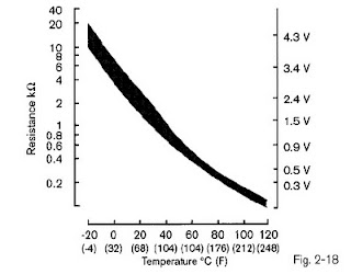
Thermistor temperature (6-8) curve graph:

Outputs
Cold Start Injector (‘Booster’) control
LED indicating Booster in operation
Value ‘live’ graphs for 8 channels
Fuel ‘Rich/Lean’ display (O2 above/below 0.45v)
Warnings
Supercharger in play – actual not dash LED
My system will give some fuel boosting and go a bit further by providing a dashboard display of 8 of the most useful engine parameters as detailed below. I would like to use a PIC16F690 running at 20MHz to do this and connect the display via RS232, but I might go mad and use an entire computer at the dash end (P1 75MHz laptop motherboard) with a 6.5" video display as basically a terminal
Sensors
1 - Throttle Position (5v)
2 – RPM (via LM2907 or similar f-to-v circuit)
The above inputs are used for the Booster circuit.
3 – AFM (5v)
4 - Boost (Add-on MAP sensor; 5v)
5 - O2 (Oxygen Sensor; 0 – 1v approx, needs 5:1 gain voltage amplifier)
O2 Sensor – Above 0.45v ‘Rich’ and below 0.45v ‘Lean’
[0.45v equates to stoichiometric air/fuel ratio of 14.7:1]
6 - ECT (Coolant Temp; 5v)
7 - IAT (Intake Air Temp; 5v)
8 - EGR (Exhaust Gas Temp; 5v)
Thermistor temperature (6-8) curve graph:

Outputs
Cold Start Injector (‘Booster’) control
LED indicating Booster in operation
Value ‘live’ graphs for 8 channels
Fuel ‘Rich/Lean’ display (O2 above/below 0.45v)
Warnings
Supercharger in play – actual not dash LED


Comments
Post a Comment