Posts

Showing posts from March, 2012

DIY Touch Screen

Image
This mini touch screen is now working (incredibly) and gives some ideas on how a screen of any size could be interfaced to the Raspberry-Pi, when it arrives. There are no special interface ICs being used here, just 4 transistors and some discrete components to let the PIC microcontroller (18F4620 in this case) control the power into the resistive panel and then read the relevant voltage to determine the X and Y coordinates of the pressed point. For simple applications like an on-screen keypad, ON/OFF control and so on, this is adequate and with improved software (averaging and use of interrupts) it could be much more accurate. The interface circuit requires 4 lines of I/O, 2 digital outputs and 2 analogue inputs. The touch screen was salvaged out of a cheap PDA which had stopped working and the graphical LCD ( GLCD ) is a standard KS0108 driven via a bespoke I2C 2-wire interface I bought on eBay although in future I would just interface one of these directly to the PIC.

Idling along

Image
The MR2 has suffered idling problems almost since the day I bought it 10 years ago. It will run along fine for a while until it warms up and then the idle gets erratic after a while, it will over-rev and then conk out at junctions just to embarrass you. Last year I cleaned up and checked over all the plugs and leads and put a new distributor cap and rotor arm on and this improved things a bit, but not much, so this year I'm looking (finally) at the induction side of things. This is the Air Flow Meter ( AFM ) on the bench. This is a heavily-made piece of kit compared to the rubbish plastic hot wire ones you get nowadays. It tested out fine and cleaned up nicely. This is the throttle body removed and cleaned up a bit. The throttle position sensor ( TPS ) is the black thing on the left and the Idle Speed Control Valve ( ISCV ) is the part on the right. The TPS seems to be okay although it needs adjusting a bit, but when I took the ISCV off, all was revealed (maybe). There are...

Back to the Future

Image
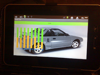
A year ago I started playing around with Google App Inventor and built a few test applications for my old £20 Android tablet . App Inventor has been taken over by MIT, who built the Apollo Guidance Computer that took men to the Moon, so they have a fair idea what they are doing and it has been re-launched in a new beta form. Now I have the Scroll Essential tablet, I decided to go back to this and it looks quite good, but the problem is that the Scroll has no drivers for either Bluetooth or Serial-USB so it can't communicate with anything. I've been investigating how to load modules (drivers) into the Android kernel, but it is no trivial task and might not be possible; a real shame as this would be the ultimate sub-£100 car computer. App Inventor (MIT) running under Windows XP

The Venturer monitor in the raw

Image
This is the pin-out for the Venturer monitor as it comes with the DVD. The little DIN plugs are 9-pin, but as you can see in my notes above, I replaced these with standard 5-pin DIN plugs carrying power, video and stereo audio (waste of time as there is only one speaker in the case!) After a while I went back to these monitors and stripped them out again. This is the inner section of one of the Venturer 6.2" monitors, the part that swivels up and down, removed from the outer case. Only 4 connections are needed to drive this and they are marked on the reverse of the circuit board - V+; GND; Video; Video GND. You can also rig your own colour and brightness controls if needed because all the necessary connections are available, but they may not be needed as the monitor defaults to usable settings. It has no back to it, but as this one will be cased or in a dashboard that didn't worry me. There is a photo here that shows the back of the monitor and the control signals (bright...